[am4show have=’p2;’]
Premium Member: You can test your knowledge with these questions first via this link.
[/am4show]
Note: If you are not sure about OSPF, please read my OSPF tutorial first.
Question 1
[am4show have=’p2;’]
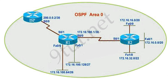
R1 routing commands:
ip route 0.0.0.0 0.0.0.0 serial0/0
router ospf 1
network 172.16.100.0 0.0.0.3 area 0
network 172.16.100.64 0.0.0.63 area 0
network 172.16.100.128 0.0.0.31 area 0
default-information originate
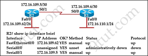
Assuming that all router interfaces are operational and correctly configured, that OSPF has been correctly configured on router R2, how will the default route configured on R1 affect the operation of R2?
A. Any packet destined for a network that is not directly connected to router R1 will be dropped.
B. Any packet destined for a network that is not referenced in the routing table of router R2 will be directed to R1. R1 will then send that packet back to R2 and a routing loop will occur.
C. Any packet destined for a network that is not directly connected to router R2 will be dropped immediately.
D. Any packet destined for a network that is not directly connected to router R2 will be dropped immediately because of the lack of a gateway on R1.
Answer: B[/am4show]
Explanation
First, notice that the more-specific routes will always be favored over less-specific routes regardless of the administrative distance set for a protocol. In this case, because we use OSPF for three networks (172.16.100.0 0.0.0.3, 172.16.100.64 0.0.0.63, 172.16.100.128 0.0.0.31) so the packets destined for these networks will not be affected by the default route.
The default route configured on R1 “ip route 0.0.0.0 0.0.0.0 serial0/0″ will send any packet whose destination network is not referenced in the routing table of router R1 to R2, it doesn’t drop anything so answers A, B and C are not correct. D is not correct too because these routes are declared in R1 and the question says that “OSPF has been correctly configured on router R2″, so network directly connected to router R2 can communicate with those three subnetworks.
As said above, the default route configured on R1 will send any packet destined for a network that is not referenced in its routing table to R2; R2 in turn sends it to R1 because it is the only way and a routing loop will occur.
Question 2
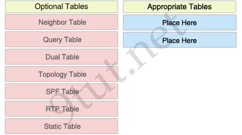
[am4show have=’p2;’]What information does a router running a link-state protocol use to build and maintain its topological database? (Choose two)
A. hello packets
B. SAP messages sent by other routers
C. LSAs from other routers
D. beacons received on point-to-point links
E. routing tables received from other link-state routers
F. TTL packets from designated routers
Answer: A C[/am4show]
Explanation
Link-state protocol uses hello packets to discover neighbors and establish adjacencies. After that, the routers begin sending out LSAs to every neighbor (each received LSA is copied and forwarded to every neighbor except the one that sent the LSA)
Question 3
[am4show have=’p2;’]Which two statements describe the process identifier that is used in the command to configure OSPF on a router? (Choose two)
Router(config)# router ospf 1
A. All OSPF routers in an area must have the same process ID.
B. Only one process number can be used on the same router.
C. Different process identifiers can be used to run multiple OSPF processes
D. The process number can be any number from 1 to 65,535.
E. Hello packets are sent to each neighbor to determine the processor identifier.
Answer: C D[/am4show]
Question 4
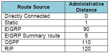
[am4show have=’p2;’]What is the default administrative distance of OSPF?
A. 90
B. 100
C. 110
D. 120
Answer: C[/am4show]
Explanation
The Administrative Distances (AD) of popular routing protocols are listed below:
Question 5
[am4show have=’p2;’]Refer to the exhibit. The network is converged. After link-state advertisements are received from Router_A, what information will Router_E contain in its routing table for the subnets 208.149.23.64 and 208.149.23.96?
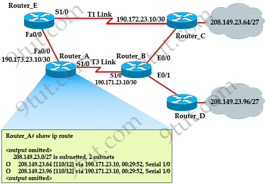
A. 208.149.23.64[110/13] via 190.173.23.10, 00:00:00:07, FastEthernet0/0
208.149.23.96[110/13] via 190.173.23.10, 00:00:00:16, FastEthernet0/0
B. 208.149.23.64[110/1] via 190.173.23.10, 00:00:00:07, Serial1/0
208.149.23.96[110/3] via 190.173.23.10, 00:00:00:16, FastEthernet0/0
C. 208.149.23.64[110/13] via 190.173.23.10, 00:00:00:07, Serial1/0
208.149.23.96[110/13] via 190.173.23.10, 00:00:00:16, Serial1/0
208.149.23.96[110/13] via 190.173.23.10, 00:00:00:16, FastEthernet0/0
D. 208.149.23.64[110/13] via 190.173.23.10, 00:00:00:07, Serial1/0
208.149.23.96[110/13] via 190.173.23.10, 00:00:00:16, Serial1/0
Answer: A[/am4show]
Explanation
Router_E learns two subnets subnets 208.149.23.64 and 208.149.23.96 via Router_A through FastEthernet interface. The interface cost is calculated with the formula 108 / Bandwidth. For FastEthernet it is 108 / 100 Mbps = 108 / 100,000,000 = 1. Therefore the cost is 12 (learned from Router_A) + 1 = 13 for both subnets -> B is not correct.
The cost through T1 link is much higher than through T3 link (T1 cost = 108 / 1.544 Mbps = 64; T3 cost = 108 / 45 Mbps = 2) so surely OSPF will choose the path through T3 link -> Router_E will choose the path from Router_A through FastEthernet0/0, not Serial1/0 -> C & D are not correct.
In fact, we can quickly eliminate answers B, C and D because they contain at least one subnet learned from Serial1/0 -> they are surely incorrect.
Question 6
[am4show have=’p2;’]What are three characteristics of the OSPF routing protocol? (Choose three)
A. It converges quickly.
B. OSPF is a classful routing protocol.
C. It uses cost to determine the best route.
D. It uses the DUAL algorithm to determine the best route.
E. OSPF routers send the complete routing table to all directly attached routers.
F. OSPF routers discover neighbors before exchanging routing information.
Answer: A C F[/am4show]
Explanation
OSPF is a link-state routing protocol so it converges more quickly than distance-vector protocol. OSPF uses cost to determine the best route. The popular formula to calculate OSPF cost is: cost = 108 / Bandwidth [ in kbps] (in fact the formal formula is: cost = reference bandwidth / configured bandwidth of interface in kbps. On Cisco routers, the reference bandwidth defaults to 100000 kbps)
Question 7
[am4show have=’p2;’]
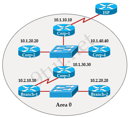
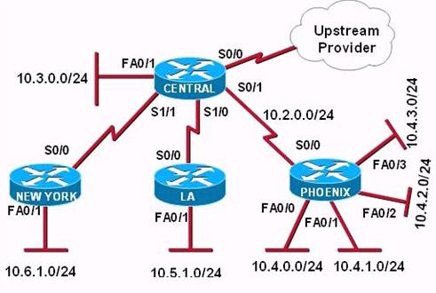
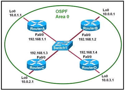
The internetwork infrastructure of company XYZ consists of a single OSPF area as shown in the graphic. There is concern that a lack of router resources is impeding internetwork performance.
As part of examining the router resources the OSPF DRs need to be known.
All the router OSPF priorities are at the default and the router IDs are shown with each router.
Which routers are likely to have been elected as DR? (Choose two)
A. Corp-1
B. Corp-2
C. Corp-3
D. Corp4
E. Branch-1
F. Branch-2
Answer: D F[/am4show]
Explanation
There are 2 segments on the topology above which are separated by Corp-3 router. Each segment will have a DR so we have 2 DRs.
To select which router will become DR they will compare their router-IDs. The router with highest (best) router-ID will become DR. The router-ID is chosen in the order below:
+ The highest IP address assigned to a loopback (logical) interface.
+ If a loopback interface is not defined, the highest IP address of all active router’s physical interfaces will be chosen.
In this question, the IP addresses of loopback interfaces are not mentioned so we will consider IP addresses of all active router’s physical interfaces. Router Corp-4 (10.1.40.40) & Branch-2 (10.2.20.20) have highest “active” IP addresses so they will become DRs.
Question 8
[am4show have=’p2;’]Which parameter or parameters are used to calculate OSPF cost in Cisco routers?
A. Bandwidth, Delay and MTU
B. Bandwidth
C. Bandwidth and MTU
D. Bandwidth, MTU, Reliability, Delay and Load
Answer: B[/am4show]
Explanation
The well-known formula to calculate OSPF cost is
Cost = 108 / Bandwidth
so B is the correct answer.
Question 9
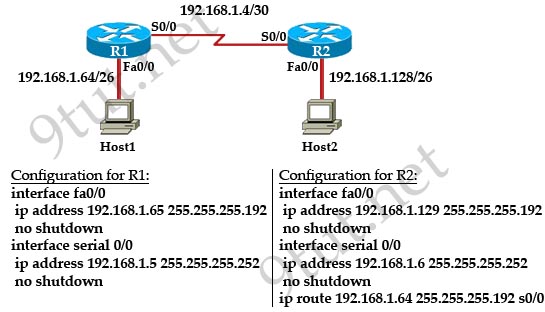
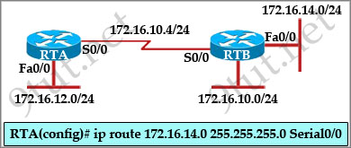
[am4show have=’p2;’]Refer to the exhibit:
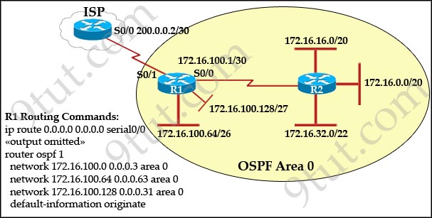
Assume that all of the router interfaces are operational and configured correctly. How will router R2 be affected by the configuration of R1 that is shown in the exhibit?
A. Router R2 will not form a neighbor relationship with R1.
B. Router R2 will obtain a full routing table, including a default route, from R1.
C. R2 will obtain OSPF updates from R1, but will not obtain a default route from R1.
D. R2 will not have a route for the directly connected serial network, but all other directly connected networks will be present, as well as the two networks connected to R1.
Answer: B[/am4show]
Explanation
The default-information originate command advertises a default route to other routers, telling something like “please send me your unknown traffic”. So in this case, besides a full routing table, R2 will also receive a default route from R1 -> B is correct.
Note: But in this question, the static route should be “ip route 0.0.0.0 0.0.0.0 serial0/1″ (not serial0/0), that may cause a routing loop.
Question 10
[am4show have=’p2;’]Which commands are required to properly configure a router to run OSPF and to add network 192.168.16.0/24 to OSPF area 0? (Choose two)
A. Router(config)# router ospf 0
B. Router(config)# router ospf 1
C. Router(config)# router ospf area 0
D. Router(config-router)# network 192.168.16.0 0.0.0.255 0
E. Router(config-router)# network 192.168.16.0 0.0.0.255 area 0
F. Router(config-router)# network 192.168.16.0 255.255.255.0 area 0
Answer: B E[/am4show]
Explanation
In the router ospf command, the ranges from 1 to 65535 so o is an invalid number -> B is correct but A is not correct.